

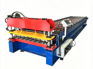
Roll Forming Machine Problems & Troubleshooting Guide
Roll forming problems fall into a handful of predictable categories: dimensional accuracy failures, surface defects, material handling issues, and hydraulic or electrical faults. This guide provides a structured approach to diagnosing root causes and applying the right fix.
Problem 1: Profile Bow and Twist
Symptoms: Finished purlins or panels bow along their length; the cross-section rotates along the longitudinal axis—visible when laid flat on a level surface.
Likely Causes and Solutions
Roller misalignment—Misaligned rollers apply uneven forming forces across the strip width, creating asymmetric residual stress that bends the profile. Fix: Perform a roller alignment check across all stations using a laser or dial indicator. Adjust lateral roller positions until all stations are concentric with the decoiler centerline.
Strip not entering square—An angled entry at the first roller station propagates asymmetry through every downstream station. Fix: Inspect the entry guide and decoiler centering. Ensure the coil is seated squarely on the mandrel with no pre-bend or lateral curl at the entry.
Inconsistent roller clearance—Varying gap between opposing rollers causes uneven work hardening across the strip width. Fix: Measure clearance at each station with a feeler gauge. Adjust to nominal specification and verify with a test strip.
Material hardness variation—Different coil hardnesses change forming force requirements mid-run. Fix: Request mill certificates with each coil. Log hardness and adjust clearance before running a new batch. Run a test strip whenever switching grades.
Problem 2: Length and Cutting Errors
Symptoms: Cut purlins are consistently over or under length; the cut face is angled rather than square.
Rotary encoder malfunction—The encoder tells the PLC when to fire the shear. A loose, dirty, or rubbing encoder disc produces incorrect position signals and fires the cut at the wrong moment. Fix: Inspect the encoder mounting bracket and coupling. Clean the disc with compressed air—no solvents. Verify cable connectors are fully seated. Run a test cut and compare measured length against the PLC setpoint.
Hydraulic shear pressure drop—On flying shear systems, insufficient pressure produces incomplete or slow cuts, resulting in angled ragged edges while material moves through. Fix: Check system pressure against the nameplate. Inspect the shear cylinder for external leakage. Verify fluid level and return filter condition.
Worn shear blades—Blades dull and chip with use, especially on high-strength material (yield up to 345 MPa). Fix: Inspect blade edges under magnification. Replace blades showing rounding, chipping, or bevel deviation per manufacturer blade-life specification.
Problem 3: Surface Defects — Scratches, Fluting, and Galling
Symptoms: Longitudinal scratches on finished profile; ridged fluting patterns under certain lighting; material pickup on roller surfaces.
Roller surface contamination—Oil, grease, or coolant residue embeds hard particles into roller surfaces and transfers scratches directly to the product. Fix: Clean all roller surfaces with an approved solvent. Eliminate the contamination source—leaking hydraulic fittings or dirty incoming coil stock.
Roller surface wear—Microscopic wear patterns accumulate with production volume, accelerated by mill debris and oxide scale. Minor scratches can be polished out by a qualified grinding shop; deep wear requires roller replacement. Monitor cumulative tonnage and inspect at manufacturer-recommended intervals.
Excessive roller pressure—Overly tight rollers generate friction heat, causing micro-welding between strip and roller (galling) and scoring the product surface. Fix: Increase roller clearance slightly. Verify strip thickness input matches actual material. Reduce forming speed when running high-strength material.
Problem 4: Material Skipping and Feeding Problems
Symptoms: Strip bunches or wrinkles between roller stations; material deviates from the feed path; servo feeder alarms or stalls.
Insufficient decoiler tension is the most common cause—low or inconsistent brake pressure lets the strip go slack between stations, forming loops. Fix: Adjust decoiler brake pressure until tension is consistent. Verify the coil is wound tightly and squarely on the mandrel.
Straightener roll misalignment or wear introduces residual strip curvature that downstream forming rollers cannot fully correct, causing buckle waves. Fix: Inspect straightener roll surfaces and bearings. Verify all rolls are parallel and correctly height-set relative to the forming centerline.
Problem 5: Punching Misalignment and Incomplete Punches
Symptoms: Holes are offset from specification; hole diameter is oversize; punches fail to fully penetrate the strip.
Punch and die clearance drift—As punches wear, clearance increases beyond the typical 5–10% of material thickness per side, producing oversized holes and eventually incomplete penetration. Fix: Measure hole diameter against spec. Check clearance with a go/no-go gauge. Replace worn punches before die damage occurs—a damaged die multiplies repair cost.
Pressure drop at the punch station—Even if main system pressure is adequate, a leak or seal failure at the dedicated punch circuit reduces penetration force below the threshold needed for the material thickness. Fix: Verify pressure at the punch station gauge. Inspect the punch circuit for leaks. Check punch cylinder seals for weeping.
Punch tip contamination—Swarf or debris on the punch tip prevents full penetration and can damage the mating die on the downstroke. Fix: Clean punch tips before each production run. Install blow-off air jets at the punch station. Implement die protection sensors to halt the machine if a punch fails to retract.
Problem 6: PLC Faults and Electrical Problems
Symptoms: Machine stops mid-cycle with a fault code; intermittent operation; HMI frozen or unresponsive.
Loose electrical connections—Vibration loosens terminal screws and connector pins over time, causing intermittent faults and potential motor damage from voltage spikes. Fix: Schedule quarterly terminal tightening inspections. Verify all power and signal terminals are to torque specification.
PLC cabinet overheating—In hot fabrication environments, cabinet temperatures can exceed PLC rated limits, causing thermal shutdown or erratic behavior. Fix: Install cabinet cooling fans. Keep ventilation openings unobstructed. Verify ambient temperature stays within the PLC's rated maximum.
Encoder signal interference—Long cable runs near welding equipment or variable frequency drives pick up electrical noise that corrupts the position signal. Fix: Use shielded encoder cable grounded at the PLC end only. Route encoder cables away from high-voltage or high-frequency noise sources.
Problem 7: Hydraulic Leaks and System Faults
Symptoms: Fluid pooling under the machine; pressure fluctuating during operation; sluggish or inconsistent actuator response.
Worn shaft seals on hydraulic cylinders—Rod seals harden and crack over time, particularly in hot environments or with extended fluid change intervals. Fix: Replace rod seals at manufacturer-scheduled intervals (typically every 2,000–4,000 operating hours). Replace the fluid simultaneously.
Loose fittings or damaged hoses—Vibration and thermal cycling loosen fitting torque progressively. Fix: Pressure-wash the area to locate the leak source. Tighten fittings to manufacturer torque values. Replace hoses showing bulging, cracking, or abrasion wear.
Contaminated hydraulic fluid—Water or particulate contamination degrades lubricity and corrodes internal components. Fix: Sample and analyze fluid. Flush and replace if contamination exceeds acceptable levels. Identify and eliminate the contamination source.
When to Call the Manufacturer
Some faults require professional support rather than field diagnosis. Roller shaft deformation or scoring requires roller cartridge replacement or machine-shop machining. PLC program corruption or parameter loss requires factory backup restore or remote diagnostics. Structural frame deformation from foundation settlement requires engineering assessment. Recurring problems with no identifiable root cause—a systematic fault tree analysis is beyond field troubleshooting scope.
Always keep a backup of PLC programs and machine parameters on external storage. Parameter loss from a power event or battery failure can take days to restore without a backup.
Frequently Asked Questions
Q: What is the most common cause of profile bow in roll forming? A: Roller misalignment is the leading cause. Even a small lateral offset at one station compounds through all downstream stations. A laser alignment check of all roller stations should be the first diagnostic step whenever bow or twist appears.
Q: How do I distinguish between encoder fault and mechanical shear fault when cuts are inaccurate? A: Measure the cut angle. A mechanical fault—worn blade or pressure drop—produces an angled cut face. An encoder fault produces cuts that are square but at the wrong length. This distinction tells you which subsystem to investigate first.
Q: Can material grade variation alone cause persistent quality problems even with a well-maintained machine? A: Yes. Coil-to-coil variation in yield strength, thickness tolerance, and surface coating adhesion all affect forming behavior. Keep mill certificates on file, log the coil batch with each production run, and adjust roller clearance when switching suppliers or grades.
Conclusion
Roll forming problems are predictable in their categories even if not in their timing. A systematic approach—observe the symptom, identify the probable cause, apply a targeted fix, verify with a test strip—resolves the majority of issues without specialist support.
Build a diagnostic reference into your shop floor documentation. Train operators to understand root causes, not just symptom-response routines. And maintain the machine rigorously: most problems described here are either prevented entirely or caught much earlier when a solid maintenance schedule is in place.
If your production line is experiencing a persistent problem that resists field diagnosis, document the full conditions—material grade, thickness, speed, ambient temperature, coil batch—and contact your equipment manufacturer with a detailed description. Thorough field data dramatically accelerates remote support resolution.
Sources: SME (Society of Manufacturing Engineers) Technical Report on Cold Roll Forming Process Troubleshooting; AISI Cold-Formed Steel Design Manual, Section on Tolerances and Quality Control; ISO 10163:1991 Cold-Rolled Steel Strip — Tolerances on Dimensions and Shape; Machinery's Handbook, 30th Edition, Section on Shearing and Blanking.






 首页
首页 产品
产品 联系
联系
